


Typical Oscilloscope Circuitry
- Cena
- 20 €
+ zaščita kupca 0,99 €
+ dostava 0,00 €
Brez skrbi, poštnino častimo mi!
Izkoristi promocijsko obdobje.

Plačaj varno in enostavno z Google ali Apple pay.
Storitev BREZ SKRBI - Denar za izdelek nakažete na nevtralni račun bolha.com. Če prejeti izdelek ni enak naročenemu ali izdelek ni bil dostavljen, vam vrnemo denar. Pred naročanjem pozorno preberite Navodila in pogosta vprašanja.
Šifra oglasa: 14120977
Osnovne informacije
- Lokacija
- Osrednjeslovenska, Ljubljana Center, Trnovo
- Stanje
- rabljeno
Opis oglasa
- Typical Oscilloscope Circuitry
Tektronix, 1966
-
trda vezava
stanje: zelo dobro
Subjects:
Cathode ray oscillographs
Light-beam oscillographs
Oscillographes
Oscillographs
oscillographs
folded leaves of plates : illustrations, graphs, plans ; 24 cm
TYPICAL OSCILLOSCOPE CIRCUITRY
INTRODUCTION
The tools of science are basically extensions of the operator`s senses. They allow us to measure quantities so large or so small that they cannot be examined directly. In many fields the oscilloscope has become an indispensable tool for the scientist or technician. It enables him to make quantitative and qualitative measurements of electrical phenomena not readily measurable by other means.
Manipulation of the front-panel controls of an oscilloscope can be learned by rote. To use the instrument to its fullest capabilities a knowledge of oscilloscope circuitry is essential.
The purpose of this book is to introduce the reader to basic oscilloscope circuitry. It is written specifically for persons who begin with only a rudimentary knowledge of electronics. An understanding of the function of electronic components is developed before the reader is introduced to circuitry. No attempt to make a complete mathematical analysis of each case will be found: rather, we have presented the mathematics necessary for the reader to understand and apply the principle set forth.
While the book has been written as outlined above, we feel that the competent technician will find much here to enhance his understanding of the instrument will benefit from the information gained.
Finally, this is a first attempt on our part to present this type of information. We welcome comments on this book and would be interested in adding information if it seems desirable.
Tektronix, Inc.
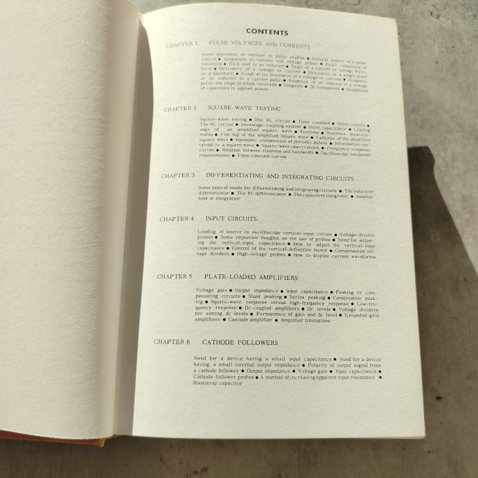
CONTENTS
CHAPTER 1
PULSE VOLTAGES AND CURRENTS
Some quantities of interest in pulse studies ● General mature of a pulse source ● Responses to current and voltage pulses ● Pulse responses of resistors ● Back emf in an inductor ● Slope of a current or voltage waveform ● Derivative or current ● Derivative at a single point on a waveform ●Graph of the derivative of a voltage or current ● Response of an inductor to a current pulse ● Response of an inductor to a voltage pulse; the slope problem reversed ● Integrals ● Dc component ● Responses of capacitors to applied pulses
CHAPTER 2
SQUARE-WAVE TESTING
Square-wave testing ● The RL circuit ● Time constant ● Other curves ● The RC circuit ● Interstage-coupling system ● Shunt capacitance ● Leading edge of an amplified square wave ● Risetime ● Risetime measurements ● Flat top of the amplified square wave ● Falltime of the amplified square wave ● Harmonic composition of periodic pulses ● Information contained in a square wave ●Square-wave observations ● Frequency-response curves ● Relation between risetime and bandwidth ● Oscilloscope bandwidth requirements ● Time-constant curves
CHAPTER 3
DIFFERENTIATING AND INTEGRATING CIRCUITS
Some typical needs for differentiating and integrating circuits ● The inductive differentiator ● The RC differentiator ● The capacitive integrator ● Another look at integration
CHAPTER 4
INPUT CIRCUITS
Loading of source by oscilloscope vertical-input circuit ● Voltage-divider probes ● Some important thoughts on the use of probes ● Need for adjusting the vertical-input capacitance ● Control of the vertical-deflection factor ● Compensated voltage dividers ● High-voltage probes ● How to display current waveforms
CHAPTER 5
PALTE-LOADED AMPLIFIERS
Voltage gain ● Output impedance ● Input capacitance ● Peaking or compensating circuits ● Shunt peaking ● series peaking ● Combination peaking ● Square-wave response versus high-frequency response ● Low-frequency response ● Dc levels ● Voltage dividers for setting dc levels ● Permanence of gain and dc level ● Grounded-giid amplifiers ● Cascode amplifier ● Amplifier limitations
CHAPTER 6
CATHODE FOLLOWERS
Need for a device having a small input capacitance ● Need for a device having a small internal output impedance ● Polarity of output signal from a cathode follower ● Output impedance ● Voltage gain ● Input capacitance ● Cathode-follower probes ● A method of increasing apparent input resistance ● Bootstrap capacitor
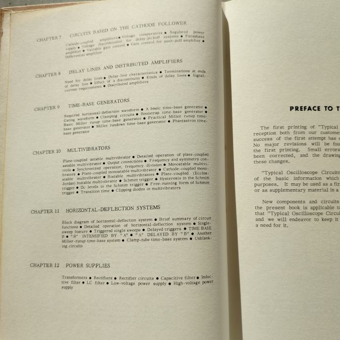
CHAPTER 7
CIRCUITS BASED ON THE CATHODE FOLLOWER
Cathode-coupled amplifiers ● Voltage comparators ● Regulated power supply ● Voltage discriminator for delay-pickoff systems ● Paraphase amplifier ● Variable gain control ● Gain control for push-pull amplifier ● Differential amplifier
CHAPTER 8
DELAY LINES AND DISTRIBUTED AMPLIFIERS
Need for delay lines ● Delay-line characteristics ● Terminations at ends of delay line ● Effect of a discontinuity ● Kinds of delay lines ● Signal-current requirements ● Distributed amplifiers
CHAPTER 9
TIME-BASE GENERATORS
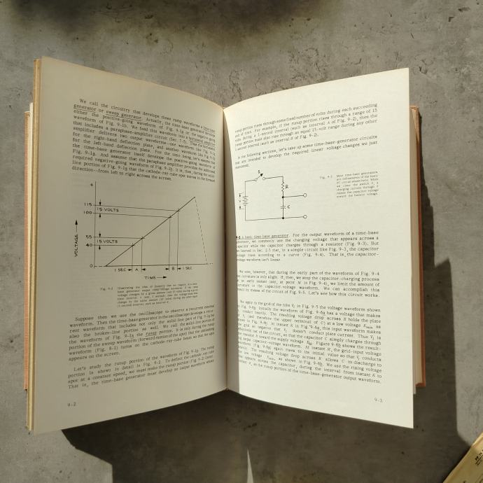
Required horizontal-deflection waveform ● A basic time-base generator ● Gating waveform ● Clamping circuits ● Bootstrap time_base generator ● Basic Miller runup time-base generator ● Practical Miller runup time-base generator ● Miller rundown time-generator ● Phantastron time-base generator
CHAPTER 10
MULTIVIBRATORS
Plate-coupled astable multivibrator ● Detailed operation of plate-coupled astable multivibrator ● Output connections ● Frequency and symmetry controls ● Synchronized operation; frequency division ● Monostable multivibrators ● Plate-coupled monostable multivibrator ● Cathode_coupled (Eccles Jordan) bistable multivibrator ● Schmitt trigger ● Hysteresis in the Schmitt trigger ● Dc levels in the Schmitt trigger ● Free-running form of Schmitt trigger ● Transition time ● Clipping diodes in multivibrators
CHAPTER 11
HORIZONTAL-DEFLECTION SYSTEMS
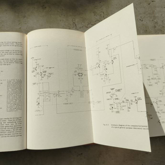
Block diagram of horizontal-deflection system ● Brief summary of circuit functions ● Detailed operation of horizontal_deflection system ● Single sweep feature ● Triggered single sweeps ● Triggered single sweeps ● Delayed triggers ● TIME BASE B ● B INTENSIFIED BY A ● A DELAYED BY B ● Another Miller-runup time-base system ● Clamp_tube time-base system ● Unblanking circuits
CHAPTER 12
POWER SUPPLIES
Transformers ● Rectifiers ● Rectifier circuits ● Capacitive filter ● Inductive filter ● LC filter ● Low-voltage power supply ● High-voltage power supply
Nonfiction, Osciloskop
---------------------------------------
Osebni prevzem je možen v centru Ljubljane ali Trnovem. Pošiljanje po poti je mogoče po predhodnem nakazilu na TRR. Poštnino plača kupec.
Prosim za sms ali sporočilo prek Bolhe, hvala.
Tektronix, 1966
-
trda vezava
stanje: zelo dobro
Subjects:
Cathode ray oscillographs
Light-beam oscillographs
Oscillographes
Oscillographs
oscillographs
folded leaves of plates : illustrations, graphs, plans ; 24 cm
TYPICAL OSCILLOSCOPE CIRCUITRY
INTRODUCTION
The tools of science are basically extensions of the operator`s senses. They allow us to measure quantities so large or so small that they cannot be examined directly. In many fields the oscilloscope has become an indispensable tool for the scientist or technician. It enables him to make quantitative and qualitative measurements of electrical phenomena not readily measurable by other means.
Manipulation of the front-panel controls of an oscilloscope can be learned by rote. To use the instrument to its fullest capabilities a knowledge of oscilloscope circuitry is essential.
The purpose of this book is to introduce the reader to basic oscilloscope circuitry. It is written specifically for persons who begin with only a rudimentary knowledge of electronics. An understanding of the function of electronic components is developed before the reader is introduced to circuitry. No attempt to make a complete mathematical analysis of each case will be found: rather, we have presented the mathematics necessary for the reader to understand and apply the principle set forth.
While the book has been written as outlined above, we feel that the competent technician will find much here to enhance his understanding of the instrument will benefit from the information gained.
Finally, this is a first attempt on our part to present this type of information. We welcome comments on this book and would be interested in adding information if it seems desirable.
Tektronix, Inc.
CONTENTS
CHAPTER 1
PULSE VOLTAGES AND CURRENTS
Some quantities of interest in pulse studies ● General mature of a pulse source ● Responses to current and voltage pulses ● Pulse responses of resistors ● Back emf in an inductor ● Slope of a current or voltage waveform ● Derivative or current ● Derivative at a single point on a waveform ●Graph of the derivative of a voltage or current ● Response of an inductor to a current pulse ● Response of an inductor to a voltage pulse; the slope problem reversed ● Integrals ● Dc component ● Responses of capacitors to applied pulses
CHAPTER 2
SQUARE-WAVE TESTING
Square-wave testing ● The RL circuit ● Time constant ● Other curves ● The RC circuit ● Interstage-coupling system ● Shunt capacitance ● Leading edge of an amplified square wave ● Risetime ● Risetime measurements ● Flat top of the amplified square wave ● Falltime of the amplified square wave ● Harmonic composition of periodic pulses ● Information contained in a square wave ●Square-wave observations ● Frequency-response curves ● Relation between risetime and bandwidth ● Oscilloscope bandwidth requirements ● Time-constant curves
CHAPTER 3
DIFFERENTIATING AND INTEGRATING CIRCUITS
Some typical needs for differentiating and integrating circuits ● The inductive differentiator ● The RC differentiator ● The capacitive integrator ● Another look at integration
CHAPTER 4
INPUT CIRCUITS
Loading of source by oscilloscope vertical-input circuit ● Voltage-divider probes ● Some important thoughts on the use of probes ● Need for adjusting the vertical-input capacitance ● Control of the vertical-deflection factor ● Compensated voltage dividers ● High-voltage probes ● How to display current waveforms
CHAPTER 5
PALTE-LOADED AMPLIFIERS
Voltage gain ● Output impedance ● Input capacitance ● Peaking or compensating circuits ● Shunt peaking ● series peaking ● Combination peaking ● Square-wave response versus high-frequency response ● Low-frequency response ● Dc levels ● Voltage dividers for setting dc levels ● Permanence of gain and dc level ● Grounded-giid amplifiers ● Cascode amplifier ● Amplifier limitations
CHAPTER 6
CATHODE FOLLOWERS
Need for a device having a small input capacitance ● Need for a device having a small internal output impedance ● Polarity of output signal from a cathode follower ● Output impedance ● Voltage gain ● Input capacitance ● Cathode-follower probes ● A method of increasing apparent input resistance ● Bootstrap capacitor
CHAPTER 7
CIRCUITS BASED ON THE CATHODE FOLLOWER
Cathode-coupled amplifiers ● Voltage comparators ● Regulated power supply ● Voltage discriminator for delay-pickoff systems ● Paraphase amplifier ● Variable gain control ● Gain control for push-pull amplifier ● Differential amplifier
CHAPTER 8
DELAY LINES AND DISTRIBUTED AMPLIFIERS
Need for delay lines ● Delay-line characteristics ● Terminations at ends of delay line ● Effect of a discontinuity ● Kinds of delay lines ● Signal-current requirements ● Distributed amplifiers
CHAPTER 9
TIME-BASE GENERATORS
Required horizontal-deflection waveform ● A basic time-base generator ● Gating waveform ● Clamping circuits ● Bootstrap time_base generator ● Basic Miller runup time-base generator ● Practical Miller runup time-base generator ● Miller rundown time-generator ● Phantastron time-base generator
CHAPTER 10
MULTIVIBRATORS
Plate-coupled astable multivibrator ● Detailed operation of plate-coupled astable multivibrator ● Output connections ● Frequency and symmetry controls ● Synchronized operation; frequency division ● Monostable multivibrators ● Plate-coupled monostable multivibrator ● Cathode_coupled (Eccles Jordan) bistable multivibrator ● Schmitt trigger ● Hysteresis in the Schmitt trigger ● Dc levels in the Schmitt trigger ● Free-running form of Schmitt trigger ● Transition time ● Clipping diodes in multivibrators
CHAPTER 11
HORIZONTAL-DEFLECTION SYSTEMS
Block diagram of horizontal-deflection system ● Brief summary of circuit functions ● Detailed operation of horizontal_deflection system ● Single sweep feature ● Triggered single sweeps ● Triggered single sweeps ● Delayed triggers ● TIME BASE B ● B INTENSIFIED BY A ● A DELAYED BY B ● Another Miller-runup time-base system ● Clamp_tube time-base system ● Unblanking circuits
CHAPTER 12
POWER SUPPLIES
Transformers ● Rectifiers ● Rectifier circuits ● Capacitive filter ● Inductive filter ● LC filter ● Low-voltage power supply ● High-voltage power supply
Nonfiction, Osciloskop
---------------------------------------
Osebni prevzem je možen v centru Ljubljane ali Trnovem. Pošiljanje po poti je mogoče po predhodnem nakazilu na TRR. Poštnino plača kupec.
Prosim za sms ali sporočilo prek Bolhe, hvala.
Zemljevid
Opomba: prikaže se približna lokacija vašega oglasa
Fletch
Vsi oglasi tega oglaševalca
Uporabnik je telefonsko številko preveril v državi Slovenija
Uporabnik ni trgovec in zanj ne veljajo določbe EU o varstvu potrošnikov.
- Naslov: 1000 Ljubljana, Osrednjeslovenska, Slovenija
- Oglas je objavljen
- 12.11.2025. ob 17:06
- Do poteka še
- Oglas je prikazan
- 916 -krat
Fletch
Vsi oglasi tega oglaševalca
Uporabnik je telefonsko številko preveril v državi Slovenija
Uporabnik ni trgovec in zanj ne veljajo določbe EU o varstvu potrošnikov.
- Naslov: 1000 Ljubljana, Osrednjeslovenska, Slovenija